Home
 Projects
Teaching Basic Analog and Digital Electronics at Undergraduate level consists of Theory Classes with hands-on-training conducted in an Electronics Laboratory equipped with Oscilloscopes, Function Generators and Regulated Power Supplies. Students identify and learn the characteristics of basic components like diodes, BJTs, FETs, OPAMPs and Digital devices.

This project presents a µcontroller based Automatic-Test-Equipment (ATE) connected to a PC which combines the functions of standard laboratory equipment providing a Low-Cost Teaching-Aid for Basic Electronics.

OVERALL ATE BLOCK DIAGRAM
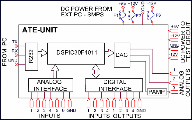
With reference to the simplified block schematic of the ATE system. In order to provide power to the ATE-Unit and the circuits under test a standard PC SMPS is used as the power supply. Three fuses are added in series with the +5V, +12V and -12V lines from the SMPS to the ATE-Unit for safety, as the SMPS though short circuit protected, is rated for a much higher current capacity than required for testing of simple circuits.

The ATE-Unit is connected to any available serial port on a PC with Windows XP operating system. It is also possible to connect the unit to the PC USB port using a USB-Serial port adapter. This serial port connection along with the "Universal Analog Hardware Test Bench" Ver1.0 software provides communication with the ATE-Unit.

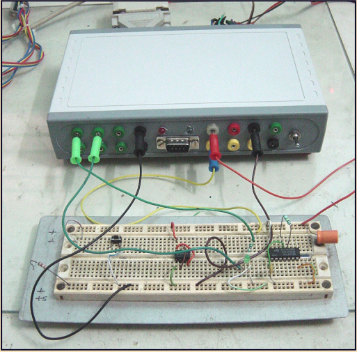
The circuit under test can be rigged up on a standard breadboard and powered from the power sockets provided. Power to the ATE-Unit and to the circuit under test comes ON only when the power switch on the ATE-Unit is activated.

The ATE-Unit provides three ±10V, 10Bit, analog output channels Vout1, Vout2 and Vout3 to the circuit under test. While Vout1 and Vout2 are Op-Amp outputs with a drive capability of ±10mA, Vout3 is power amplified to provide a drive of ±200mA. The maximum throughput rate is 20 kHz.

Six ±10V, 10Bit analog input channels (Ain1-
Ain6) with an input impedance of typically 1MΩ are provided to read back analog data from the circuit under test. The maximum sampling rate is 2 mega-samples/sec.

Four buffered digital I/O channels (Dout1-Dout4 and Din1-Din4) are also provided for connection to the circuit under test.

TYPICAL EXPERIMENTAL RESULTS
SMPS CIRCUIT AND  BOARD
SUMMARY

The figures show typical experimental results obtained for devices, op-amp and digital circuits and a DSO display in capture mode. Several experiments including plotting of the B-H curve of Ferrites are also possible.

As an alternative to using expensive laboratory equipment, this project presents a very Low-Cost micro-controller based ATE system for carrying out experiments in Basic Electronics at Undergraduate level.

The simple hardware can be fabricated by undergraduate students and novice engineers themselves.

By providing technical data and executable software free for non-commercial use I wish to encourage the computer aided teaching of basic electronics.

DOCUMENTATION, CIRCUIT DIAGRAMS,  DESIGN DATA, VB.NET SOFTWARE, DSPIC30F4011 HEX CODE

All data required for fabrication, programming and operation of the "Universal Analog Hardware Test Bench" is provided free for non-commercial use as a winrar archive.

ATE_Final_25 Sept 12.rar