

Introduction:
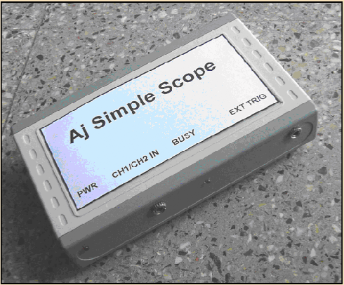
This unit is designed to compliment the Aj-SigGen-PS and serve as a teaching aid for budding engineers, electronic enthusiasts and hobbyists.
This USB connected unit implements a microcontroller based 2-Channel Oscilloscope providing continuous sampling rates up to 100 ksps and 20 Msps using equivalent time sampling. Common DSO features such as spectrum analysis, waveform capture and data saving are provided. The input range is ± 12V with additional gain settings of X2 and X5. Trigger and sweep options are also provided.
This USB connected unit implements a microcontroller based 2-Channel Oscilloscope providing continuous sampling rates up to 100 ksps and 20 Msps using equivalent time sampling. Common DSO features such as spectrum analysis, waveform capture and data saving are provided. The input range is ± 12V with additional gain settings of X2 and X5. Trigger and sweep options are also provided.
Block Schematic and Function Description
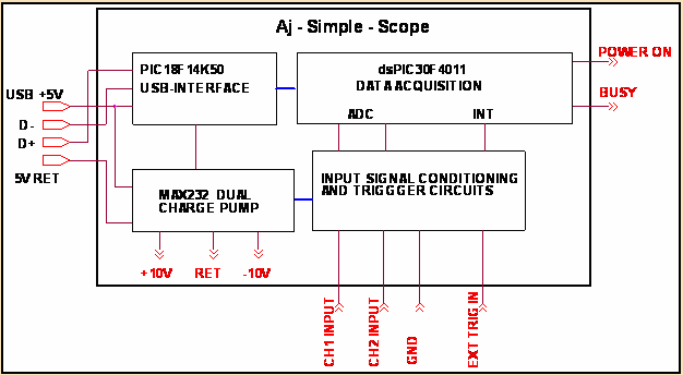
The figure shows the simplified block schematic of the system. For ease of portability the unit is powered and controlled from the USB port of a PC.
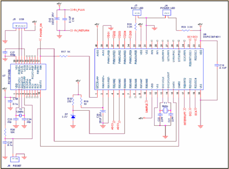
A PIC18F14K50 and dsPIC30F4011 microcontrollers are used to provide the functionality of the unit.
The first PIC microcontroller implements the following functions:
A PIC18F14K50 and dsPIC30F4011 microcontrollers are used to provide the functionality of the unit.
The first PIC microcontroller implements the following functions:
· Communicates with the host PC for enumeration as a USB to UART device
· Sets up the unit as a 200mA device
· Switches on power to the DC-DC converter
· Acts as a USB communication interface to the second PIC
The second PIC microcontroller implements the main Oscilloscope Functions
· Analog to Digital conversion of the CH1 & CH2 signal conditioned inputs at the required sampling rates
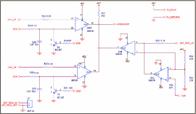
· Trigger interrupt handling
· Responding to serial commands from PIC1 and sending back the acquired data.
· A Busy signal is also generated
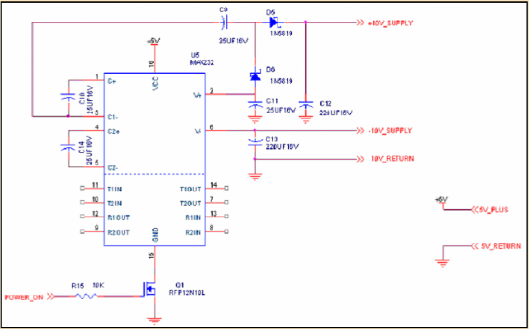
The dual-charge pump circuitry of the MAX232 is used as a DC-DC converter to provide a nominal ± 10V to all the analog circuitry.
Software on the PC Host:
A Visual Basic .Net 2.0 based GUI program is used to control the functions of the Aj-SigGen - PS unit. An Aj_SigGen.exe along with associated USB driver files has been tested for compatibility with Windows XP and Windows 7 with .net 2.0.
GUI
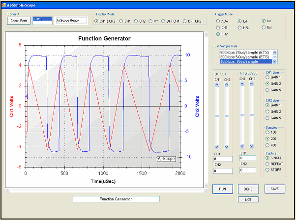
The GUI based Windows software on the Host PC permits checking for available COM ports and connecting to the port on which the hardware is connected.
Once connected the hardware unit responds with a ready signal.
Display and trigger modes, sampling rate, channel gains, channel offset trigger offset and number of samples can be set using the simple controls.
The RUN button initiates the signal capture single, repetitive or over-plotted
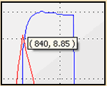
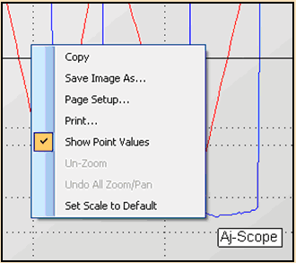
Values of data at the mouse cursor are automatically displayed.
The waveform caption can be entered and the figure stored as an image file. Image zoom, copy, print and save modes are provided.
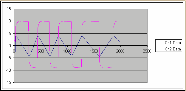
Data can be stored in a .csv file using the SAVE option. Further processing can be carried out in MS EXCEL. A Plot in EXCEL is recreated based on saved data
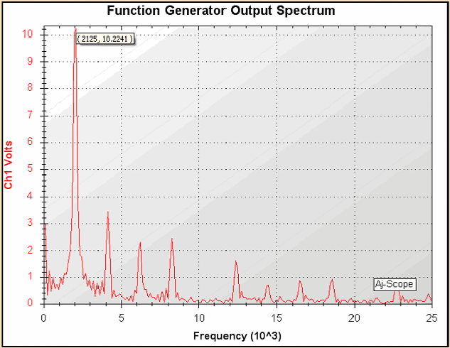
A DFT (discrete furrier transform) can be carried out to show the frequency spectrum of captured waveforms.
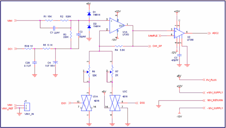
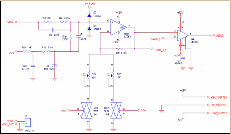
Circuit Diagram of CH1 signal conditioner circuitry
Circuit diagram of CH2 signal conditioner circuitry
Circuit diagram of MAX232 as a DC-DC converter
Circuit diagram of Trigger circuitry
Circuit diagram of Processor circuitry
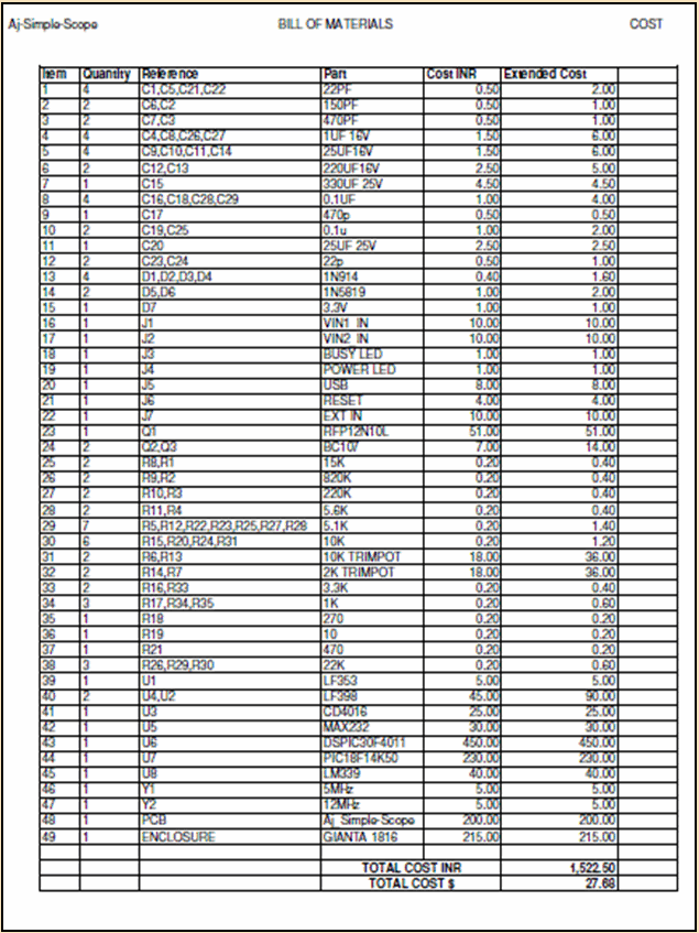
Bill of Materials
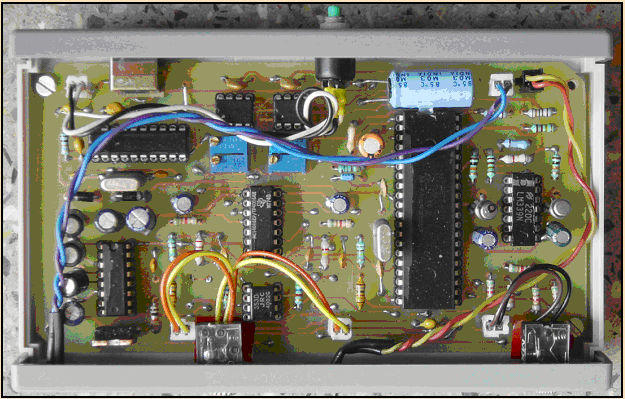
Component Layout
Software, PCB's and Documentation
Complete documentation and the software executive files are provided in
Aj-Simple-Scope_SW_and_Docs.rar
Contains:
1. Technical Document Aj-Smple-Scope_Tech-Manual-Final.pdf
2. Folder containing vb.net2 files Aj_Simple-Scope_VB.NET2
Aj_Scope.exe
Aj_Scope.pdb
Aj_Scope.xml
ZedGraph.dll
Aj_Scope.ico
3. Fuze file for PIC1 Aj_Scope_PIC1_USB.hex
4. Fuze file for dsPIC Aj_SimpleScope_dsPic.hex